Sheet Metal Fabrication - The Complete Guide
- Why sheet metal is a product designer's friend
- Materials and thickness choices
- Flat patterns and bend allowances
- Cutting - laser, waterjet and CNC punching
- Bending and forming on a press brake
- Details that make assemblies sane
- Joining - welding, hardware and adhesives
- Finishes - powder, anodize, chem film
- Tolerances and datums for real parts
- DFM for cost and repeatability
- What drives quotes and lead time
- QA and measurement - what to check
- Case notes from the shop
- FAQ
Why sheet metal is a product designer's friend
Sheet parts can be fast, strong and attractive with the right finish. A single flat blank becomes an enclosure, bracket or chassis after a few bends and hardware hits. Tooling is light compared to molding, changes are affordable, and you can scale from one to thousands without changing the core process. The hidden work is in getting bends, holes and hardware to cooperate rather than fight.
Materials and thickness choices
We pick material by stiffness, corrosion resistance, weight, conductivity and finish. Thickness is a function of span and load, but also the fasteners and threads you plan to use.
| Material | Common gauges | Where it shines | Watch outs |
|---|---|---|---|
| Mild steel | 1.0 mm - 3.0 mm | Stiff, cheap, ideal for powder coat and welding | Needs finish for corrosion, heavy vs aluminum |
| Stainless steel 304/316 | 0.8 mm - 2.5 mm | Corrosion resistance, food and medical, raw cosmetic | Work hardens, more springback, slower to cut |
| Aluminum 5052/5083 | 1.0 mm - 4.0 mm | Lightweight, bends nicely, anodize options | Softer threads, TIG weld skill needed for cosmetics |
| Aluminum 6061 | 1.5 mm - 6.0 mm | Stiffer than 5052, good for machined features | Cracks if bent tight - use larger inside radii |
| Copper and brass | 0.5 mm - 2.0 mm | Conductivity, aesthetics, easy forming | Cost, fingerprints, patina unless sealed |
Gauge charts vary - always model in millimeters. Ask the shop for their default bend radii and K factors for each alloy and thickness.
Flat patterns and bend allowances
Flat pattern size is not a guess. When metal bends, it stretches on the outside and compresses on the inside. Somewhere in the middle is a neutral axis that does not change length. We use a K factor to place that axis as a percentage of thickness. The result is a bend allowance that tells you how much material a bend consumes in the flat.
Designers do not need to hand calculate every bend. What you need is consistency. Use the shop's K factor library in your CAD so flats match the brake. Model internal bend radii that match the brake tooling - typically 1 x material thickness for 5052 aluminum, 1 to 1.5 x for mild steel, and larger for 6061 and stainless.
Cutting - laser, waterjet and CNC punching
Laser cutting is the default for most work. It is precise, quick to program and handles tabs, slots and small features well. Kerf is small and edge quality is good. Waterjet has no heat affected zone and will not harden edges, useful for thick or exotic alloys. It is slower and has a wider kerf. CNC punching is fast for perforations, louvres and formed features, and it can be cheaper for volume patterns because the tool stamps instead of burning.
We add micro-tabs in long cuts to prevent tip-up, place lead-ins away from cosmetics, and keep minimum web widths sensible so heat does not twist thin ligaments.
Bending and forming on a press brake
Brakes bend by pressing a punch into a die with the metal between them. Inside radius is mostly a function of die opening and material. Springback means the part relaxes after the pressure is released. We compensate by overbending slightly, or by choosing tooling that sets the inside radius where we want it. For sensitive skins, we use urethane film or non-marking tooling.
Order of operations matters. Bend the small flanges before big ones that would block the punch. Put PEM hardware in before bends that would block the anvil. Add relief notches at bend intersections so material does not tear or bulge.
Details that make assemblies sane
- Bend reliefs - small rectangular or tear-drop cuts at the ends of a bend to prevent tearing and cosmetic bulge.
- Hems - folded edges that are safe to touch and stay straight. Open hems reduce sharpness, closed hems add stiffness.
- Lances and tabs - self locating features that make assembly quick and repeatable.
- PEM and rivet nuts - provide threads without tapping. Choose lengths that do not telegraph through thin skins.
- Slots - give adjustment where tolerances stack, for example mounting holes to a machined chassis.
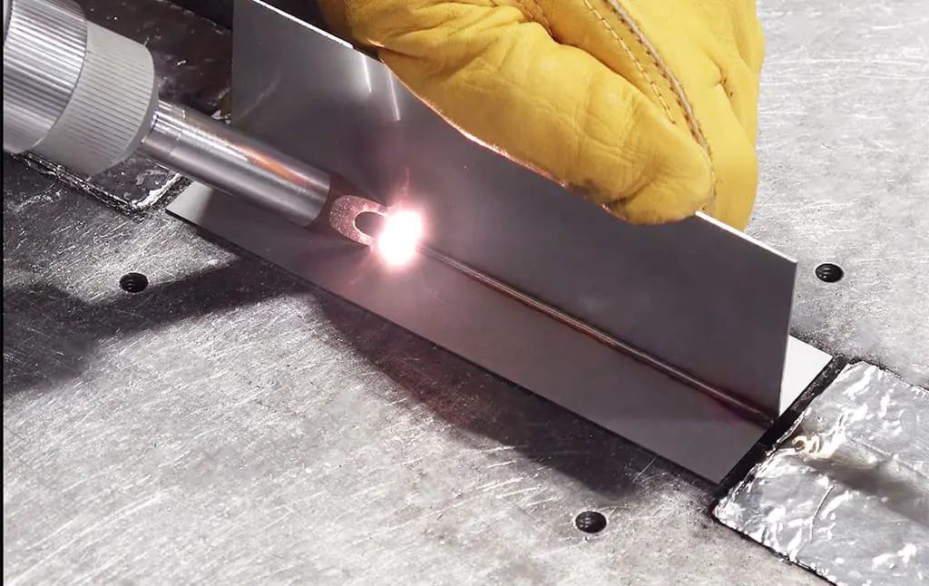
Joining - welding, hardware and adhesives
MIG and TIG welding are common. MIG is fast for steel and thick aluminum. TIG gives better cosmetic control and thin sheet capability. Warping is managed with stitch patterns, fixtures and chill bars. For stainless cosmetic seams, we often back purge and finish with controlled brushing. Spot welding is perfect for overlapping flanges in steel, fast and clean. Mechanical hardware like PEM nuts, studs and standoffs turns thin sheet into a threaded assembly. Rivets and structural adhesives join dissimilar metals and spread load without heat distortion.
Finishes - powder, anodize, chem film
Powder coat is robust and hides minor fabrication marks. Mild steel and stainless take powder well with proper prep. Anodize works for aluminum and comes in cosmetic and hard variants. Cosmetic anodize wants a uniform grain finish first. Chromate conversion or chem film gives aluminum a conductive, corrosion resistant surface that is paint ready. For stainless, a brushed grain or bead blast finish can be the final look without coatings.
Masking adds cost and risk. We design features so critical ground points, bearing bores and sliding interfaces are naturally protected from coating rather than relying on complex masks.
Tolerances and datums for real parts
Sheet is not a rigid block. Expect different behavior along and across the grain. Holes close to bends will walk slightly unless reliefs are used and the bend sequence is controlled. We dimension from functional datums that the shop can hold, not from arbitrary faces. For example, we will call out the distance from a connector cutout to a mounting hole pattern on the same flat before any bend. We check enclosure fit by assembling against the mating parts, not by chasing every single dimension with calipers.
| Feature | Good starting tolerance | Notes |
|---|---|---|
| Laser cut holes and slots | ±0.15 mm | Size and edge quality depend on thickness and kerf |
| Bend angle | ±1 degree | Requires consistent tooling and program |
| Bend to hole location | ±0.25 mm | Dimension from the flat before bending |
| Overall enclosure size | ±0.5 mm | Large panels may move with heat and handling |
DFM for cost and repeatability
Every extra setup and tool change costs time. We combine bends on the same tool where possible. We align tabs and slots so they nest, then we let the laser cut do the locating work for the press brake. We use standard radii and punches the shop already owns. We avoid tiny notch details on exterior edges that chip during handling. We add carry tabs that are trimmed after powder so parts do not touch the rack at cosmetic faces.
What drives quotes and lead time
Material thickness and grade drive cutting time. Number of bends and unique tool setups drive brake time. Hardware count adds press hits. Welding adds hours and risk for warp. Powder adds curing time and a batch constraint. Speed comes from simple nesting, repeatable bends and minimal post-processing. If we quote fast, it is because the drawing is clear, the finish is specified, and the flat pattern makes sense.
QA and measurement - what to check
We verify critical hole patterns in the flat before bending. We use angle gauges at the press to keep bends honest. After finish, we assemble with the mating parts and check that doors close, bosses align and ground points are clean. Cosmetic inspection is a light booth and a checklist - powder build, orange peel, pinholes and edge coverage.
Case notes from the shop
Electronics enclosure - laser cut 1.5 mm 5052, PEM hardware before bends, all exterior edges hemmed for safety, powder coat with masked ground pads. The drawing called out carry tabs so the rack never touched the cosmetic faces.
Stainless kiosk frame - 2.0 mm 304 with long seams TIG welded and brush finished. We used fixtures and chill bars to control warp, then passed on bead blasting to keep the grain crisp under a clear coat.
Aluminum battery tray - 3.0 mm 5052 with flanged holes and ribs for stiffness, chromate conversion for conductivity and corrosion protection. Rivet nuts kept serviceability without heat distortion.
FAQ
Can I mix machined features with sheet parts - Yes. We commonly machine a base plate with precision bores and bolt a formed shell on top.
What minimum flange can I bend - As a rough guide 2x thickness for a stable flange. Tighter is possible with special tooling and careful reliefs.
How do I avoid oil canning on big panels - Add shallow ribs, hems or a bead feature. Orient the grain smartly and think about how powder will shrink during cure.
Should I anodize before or after forming - After forming for tight bends. Pre-anodized sheet can crack on tight radii and shows stretch marks.