CNC Machining Design Guide
- Mindset - reverse thinking order of operations
- Tooling - cutters, drills, taps, thread mills and inserts
- Workholding and datum strategy
- Toolpaths - adaptive, stepdowns, climb vs conventional
- Feeds, speeds, chipload and deflection
- Geometry limits and DFM
- Materials - aluminum, steel, stainless, brass, plastics
- Tolerances, GD&T, edge breaks and deburring
- Surface finishes and handling
- Probing, inspection and process control
- Cost levers and quoting
- Common mistakes and fixes
- FAQ
Mindset - reverse thinking order of operations
We start at the end. What does the final part look like on the drawing after finishing and inspection. Then we walk backward to the first operation. This reverse thinking avoids painting ourselves into a corner with unreachable faces or trapped burrs. Engineers list every face that must be cut, how it will be held when that face is exposed, and which datum will reference the cut.
Order of operations aims to lock datums early and protect cosmetic faces. Machine the reference plane and locating edges first. Add features that help with later workholding like soft jaw registers or dowel holes. Leave thin features for last when the rest of the part is stiff. For parts with tight bores and flats, rough everything, stress relieve if needed, then finish the tight features in a single setup referenced to the functional datum.
Tooling - cutters, drills, taps, thread mills and inserts
Pick tools that match material and geometry. A simple set gets most jobs done: roughing end mill, finishing end mill, small end mill for internal radii, spot drill, drill set, reamer for tighter bores, countersink, tap or thread mill. For production add indexable face mills and high-feed roughers.
| Tool | When to use | Notes |
|---|---|---|
| Roughing end mill | Stock removal | Chip breakers reduce load, leave 0.2 to 0.5 mm for finish |
| Finishing end mill | Final walls and floors | Sharp, more flutes, light stepdown and stepover |
| Small end mill | Internal corners | Use shortest stickout to fight deflection |
| Drill + reamer | Precision bores | Drill undersize, ream to final |
| Tap | Fast threads | Great for through holes, careful with blind holes |
| Thread mill | High quality threads | Slow but precise, one tool covers sizes with different passes |
| Face mill | Large flat faces | Indexable inserts, great for aluminium with polished geometry |
Material matters. Aluminium likes sharp polished tools and high RPM with flood or mist. Stainless prefers lower SFM and strong chip evacuation. Plastics need sharp tools and low heat. Brass cuts beautifully with sharp edges and moderate chipload.
Workholding and datum strategy
Good parts start with good fixturing. Choose a datum scheme A, B, C that is practical to reference in each setup. Use soft jaws to match odd profiles and keep clamp forces low but reliable. Vacuum works for thin plates when you include fences and tabs. Dowel pins and rest pads make repeatable second ops trivial.
- Setup 1 - clamp raw stock, face and square, cut locating features for Setup 2.
- Setup 2 - flip into soft jaws keyed by Setup 1 features. Finish walls and pockets.
- Setup 3 - if needed for back features, use a subplate and dowels to repeat position.
Toolpaths - adaptive, stepdowns, climb vs conventional
Adaptive clearing keeps chipload constant and saves tools. Leave adequate stock for finish passes. For aluminium, climb milling gives better surface and tool life. For steels, climb is still preferred but watch backlash in older machines. Rest machining picks up material left by larger tools.
- Pockets - adaptive rough, then 2D contour and scallop for walls and floors.
- Bosses - circular adaptive followed by finish contour.
- 3D surfaces - constant stepdown with small stepover, then parallel finishing.
- Chamfers - a dedicated chamfer tool gives consistent edge breaks.
Feeds, speeds, chipload and deflection
Start with manufacturer SFM and chipload tables, then tune by ear, chip shape and spindle load. Use calculators to balance stickout, flute count and stepover. Deflection grows with stickout cubed - keep tools short. For small end mills in deep pockets reduce stepdown and increase coolant flow.
| Dial | Effect | When to move |
|---|---|---|
| SFM (surface speed) | Heat and tool life | Decrease in stainless, increase in aluminium |
| Chipload | Cutting efficiency | Increase until burrs shrink, back off if chatter |
| Stepdown/Stepover | Tool load and finish | Small tools need lighter cuts |
| Coolant | Chip evacuation | Boost in deep pockets and gummy materials |
Geometry limits and DFM
| Feature | Good | Better | Notes |
|---|---|---|---|
| Internal corner radius | 1.5 mm | 2 to 3 mm | End mills are round |
| Pocket depth | Up to 6x tool dia | Step or long reach | Stability and chatter |
| Thin wall | 1.0 mm | 1.5 mm with ribs | Material dependent |
| Thread depth | 1x diameter | 1.5x diameter | Most strength gained early |
Design parts for the tools you want to use. Increase fillet radii, avoid tiny slots and plan generous chamfers. If you need a sharp inside corner, consider a wire EDM or redesign the feature.
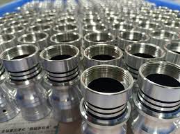
Materials - aluminum, steel, stainless, brass, plastics
- 6061 T6 - the default. Machines cleanly, anodizes well. Use polished tools and climb milling.
- 7075 - stronger, beautiful finish, watch corrosion. Great for structural parts.
- 304/316 - tough, work hardens. Lower SFM, sharp tools, rigid setups.
- Brass - dream to cut. Watch burrs, deburr gently.
- POM, ABS, PC - sharp tools, avoid heat, use air blast, clamp carefully to prevent creep.
Tolerances, GD&T, edge breaks and deburring
Default shop tolerance is plus or minus 0.1 mm unless noted. Call out only what function needs. Use GD&T for critical relationships like perpendicularity and true position. Always specify edge breaks - for example "Break edges 0.2 to 0.5 mm" - so technicians know expectations.
Deburring is not magic. Design to reduce burr traps. Use chamfers where parts assemble and plan a manual pass where necessary. For thread quality on small holes consider thread milling instead of tapping when precision matters.
Surface finishes and handling
Anodize for aluminium, bead blast for satin, powder coat for steels. Mask fits and threads. If you need tight fits after finish, plan to machine those faces after coating or keep them protected with masking and plugs.
Probing, inspection and process control
Use probing to set work offsets and verify critical features mid cycle. On the bench, verify datum scheme with a CMM or height gauge and gauge blocks. Build an inspection sheet that mirrors the drawing - the fastest way to keep parts flowing is to remove ambiguity.
Cost levers and quoting
- Reduce setups - design for two setups with soft jaws.
- Increase fillet radii - larger tools run faster and last longer.
- Consolidate tools - fewer tools means shorter cycle and less chance of errors.
- Specify reasonable tolerances - only where function requires.
- Choose friendly materials - 6061 over 7075 unless strength demands it.
Common mistakes and fixes
- Knife edges on thin walls - add thickness or chamfer.
- Tiny internal corners - increase radii or change geometry.
- No plan for second setup - design registers early.
- Finishing before roughing all sides - parts move, leave finish for last.
- Unspecified edge breaks - add a standard note to drawings.
FAQ
Should I tap or thread mill
Tap for speed and cost, thread mill for precision, difficult materials or small lots where you want control of pitch diameter.
How do I stop chatter in deep pockets
Shorten stickout, reduce stepdown, increase RPM slightly, use a variable flute tool and add more coolant or air.
What surface finish callout should I use
For general parts Ra 1.6 to 3.2 micrometers is common. For cosmetic faces, combine light bead blast with anodize.