Injection Molding - The Complete Guide
- Why molding is still the backbone
- Anatomy of a mold
- The molding cycle - what actually happens
- DFM that prevents pain later
- Parting line, slides and lifters
- Cooling design and why it rules cycle time
- Venting, shear and weld lines
- Tool steels, inserts and maintenance
- Finish, texture and draft
- Quality control and measurement
- Automation, sensors and smart molds
- Sustainability and recycled content
- Where molding beats CNC and 3D printing
- FAQ
Why molding is still the backbone
Molding is unapologetically industrial. Once a part is designed correctly and the tool is right, you get repeatability, speed and reliable cosmetics at a cost per part that drops as volume rises. The compromise is up-front tooling and discipline around geometry, gating and cooling. It pays back - that’s why everything from toothbrushes to surgical housings is molded.
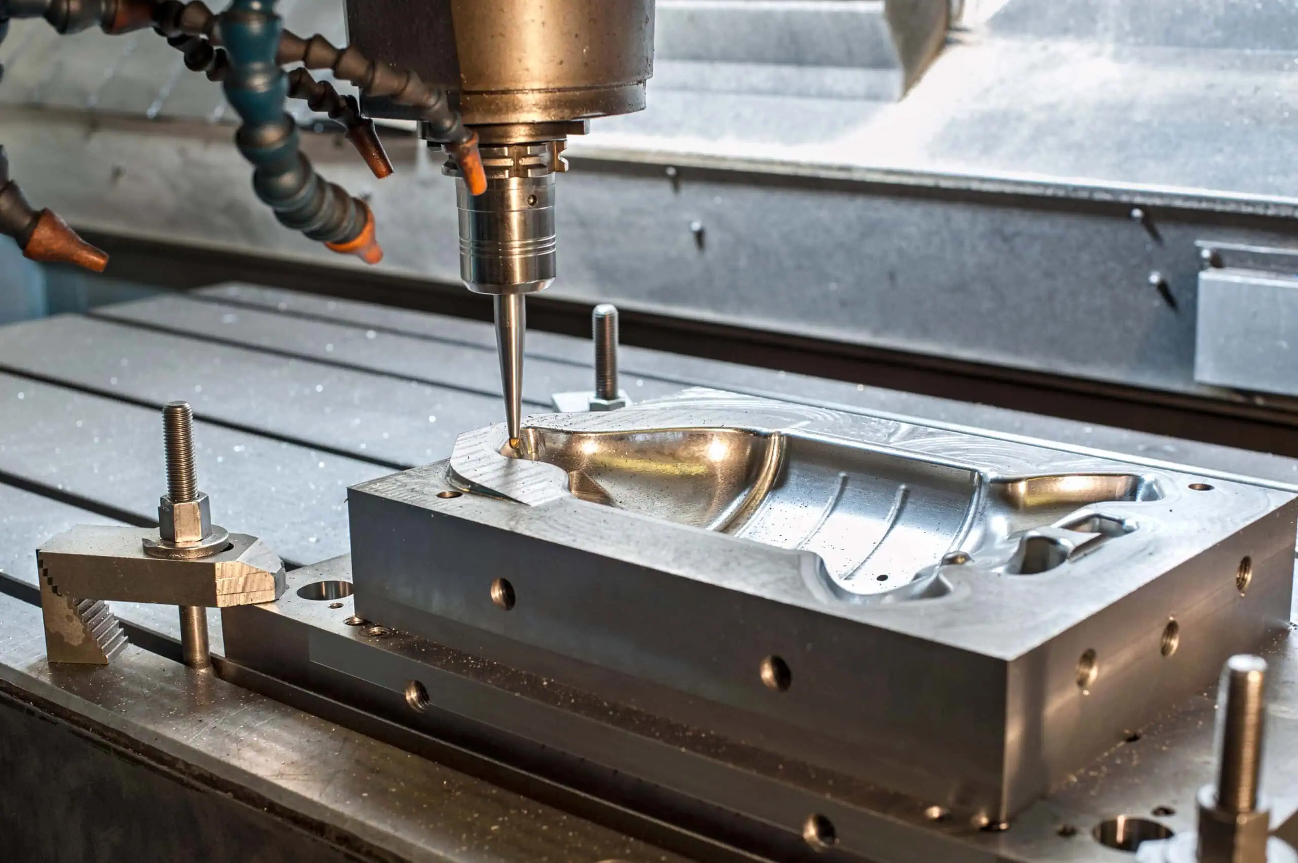
Anatomy of a mold
Think of a mold as a precision heat exchanger wrapped around a cavity. Core and cavity form the part, inserts solve local problems, cooling removes heat without creating hot spots, vents let air out, and steel moves (slides and lifters) to release undercuts. Ejectors push the part out without hurting what the customer sees. It’s all deliberate.
We like to sketch a cross-section early with the parting line, gate, main cooling, vents and ejector style marked. Everyone can then reason about where steel must be, how it moves, and what surfaces must stay pristine.
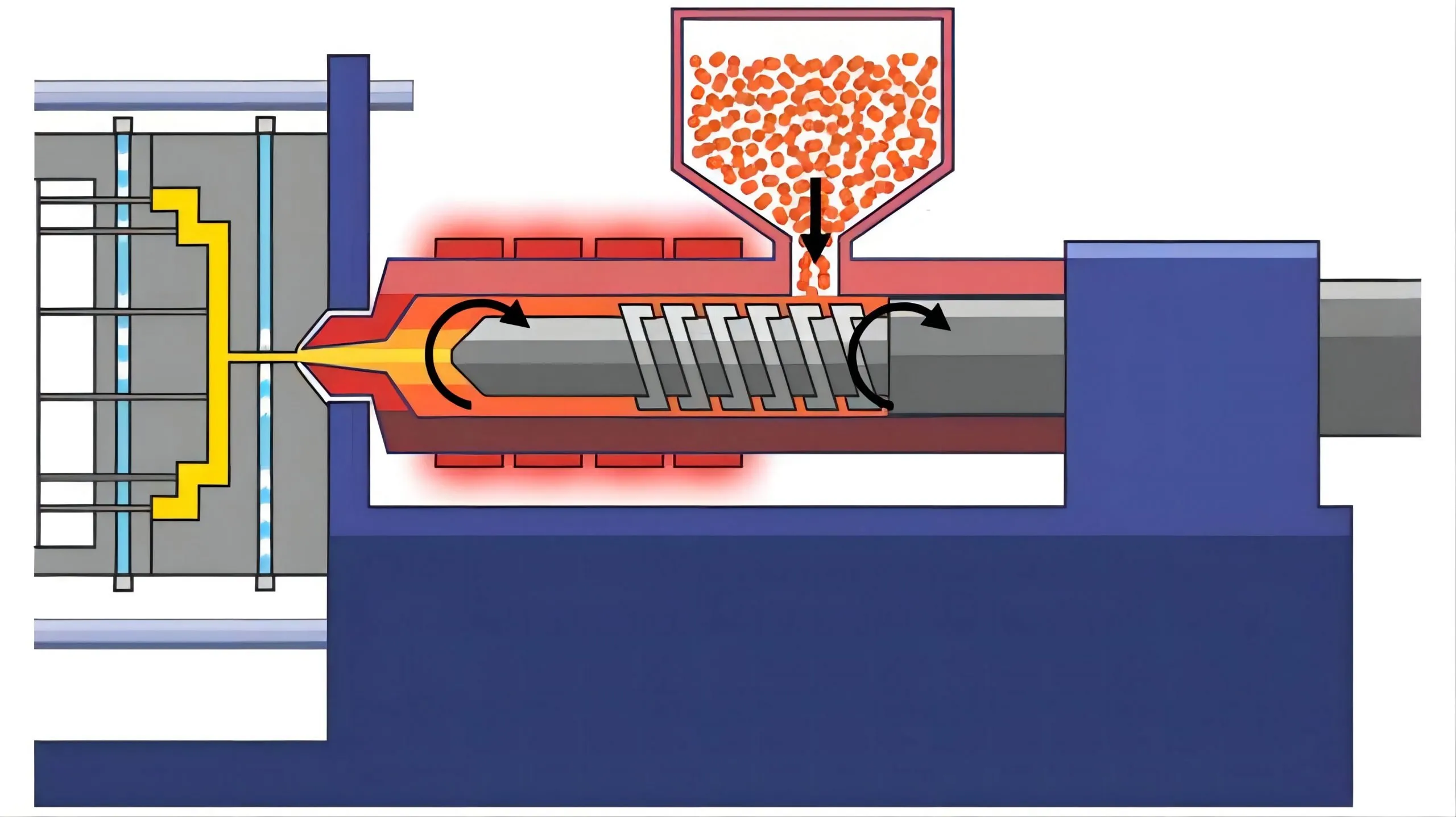
The molding cycle - what actually happens
The screw plasticizes pellets into a homogenous melt. The machine closes, injects at velocity, then holds pressure to pack more material as the gate freezes. Cooling dominates time: if the cooling is even, the part shrinks evenly and ejects cleanly. Ejectors move, the tool opens, and either a robot or an operator removes the part. Every dial on the machine maps to physics in the tool.
DFM that prevents pain later
Great molded parts are designed to be molded. That means uniform walls, generous fillets, and draft. It also means acknowledging where ejector pins can touch and where they cannot. We place logos and textures to help, not fight, ejection. We avoid deep, narrow ribs with blunt roots that sink. We merge tiny bosses into supporting ribs so there’s somewhere for strength to come from. We choose fasteners that don’t require razor-thin bosses.
Before steel is cut, we run a quick fill/pack check. We’re not trying to win a CFD prize - we just want to catch obvious air traps, weak knit lines, and a gate that points at the cosmetic face.
Parting line, slides and lifters
The parting line is the seam where the mold opens. Place it where a witness line is acceptable, and where it helps draft rather than fights it. Undercuts are solved with moving steel: slides (side actions) move horizontally; lifters kick out of the core while moving away. Both need space and add cost, but they unlock designs that would otherwise force awkward geometry.
For screw bosses, a collapsible core or unscrewing mechanism can form internal threads cleanly. For snap features, we let the slide carry the detail so we keep the cosmetic core surfaces clean and simple.
Cooling design and why it rules cycle time
Cooling is the quiet boss. Straight drilled channels handle simple parts. Baffles and bubblers push flow into deep cores. For tight cosmetics or cycle-critical parts, conformal cooling inserts follow the geometry and pull heat out evenly - expensive to make, cheap to run. When a part sinks or warps, nine times out of ten the fix is a cooling re-think or a wall thickness correction, not a heroic packing pressure curve.
Venting, shear and weld lines
Air must escape. Tiny vents at the end of flow and near ribs prevent burn marks and short shots. Shear heats the melt; too much shear at the gate can blush a cosmetic face. Where flows meet, you get a weld line - if it crosses a load path, we’ll move the gate or tweak process to improve strength. On clear parts, we’ll use fan or film gates to keep the optical path clean.
Tool steels, inserts and maintenance
Aluminum cuts fast and is easy to modify - perfect for prototypes and moderate volumes, but watch wear with glass-filled resins. P20 is the workhorse for general production. H13 and other hardened steels are for long life and abrasive fillers. We often drop beryllium-copper inserts into hot spots to get better cooling without rethinking the whole tool. Maintenance matters: regular cleaning, polishing high-wear pins and replacing seals keeps dimensions and cosmetics stable over the life of the program.
| Steel | Typical use | Life ballpark | Notes |
|---|---|---|---|
| Aluminum | Proto/bridge | 5k–50k shots | Fast to cut, easy to tweak, watch abrasive resins |
| P20 | General production | 100k–500k | Good balance of cost and life |
| H13/hardened | High volume/filled resins | 500k–1M+ | Slow to cut, very durable |
Finish, texture and draft
Finish lives in the steel. SPI grades give common language from optical polish to matte. Heavy textures hide scuffs and fingerprints but need more draft - think 2–3 degrees or more. If the brand wants a sharp line next to a textured field, we’ll plan the parting line carefully so there’s no mismatch or flash halo right where the eye goes.
Quality control and measurement
T1 samples are for learning. We map defects, tweak process, and document any steel changes. T2 is where we confirm critical dimensions with a CMM or high-quality gauges and lock cosmetic standards with the client - photos, light booth, the works. During production, we run simple SPC on critical dimensions instead of checking everything on every shot. Traceability matters: box labels include cavity, date and process revision so a mystery later is solvable in minutes, not days.
Automation, sensors and smart molds
Robots make parts consistent, not just fast - they grab at the same place every cycle and avoid scuffs. End-of-arm tools can trim gates, stack parts and present them for inline checks. Smart molds embed thermal or pressure sensors in hot zones so the machine can hold a tight window on pack and cool. It’s not about buzzwords; it’s about fewer rejects and stable cycle time.
Sustainability and recycled content
Regrind is useful when specs allow - we define a percentage and stick to it. Recycled grades have improved a lot; we test early for color consistency and mechanicals. All-electric machines are efficient, and smart cooling cuts time and energy per part. If sustainability is a goal, we lock resin choice and process window before tooling so we’re not fighting physics later.
Where molding beats CNC and 3D printing
If you need a steady stream of identical parts with defined cosmetics, molding wins once you cross a modest volume. CNC is perfect for thick, precise, lower-quantity parts. Additive shines when geometry is impossible in a tool or when iteration speed matters more than unit cost. We’ve even blended: printed preforms that drop into a simple mold for final surfaces and features.
FAQ
How do I know if an undercut needs a slide - If a feature traps the part on the core, it needs moving steel or a redesign. We’ll flag these in the first DFM.
Can we avoid weld lines - We can move and improve them. Gate changes and temperature tweaks help; for structural areas we change geometry or reinforce.
What’s the most common cause of long cycle time - Conservative cooling. Even simple tools benefit from thought-out cooling and uniform walls.
Do we always need a hot runner - No. For mid volumes, a cold runner can be simpler and more robust.